

Introduction: Color Coded Clock - Colors Show the Time


The clock I built in this project is based on a fact that has been researched for some time, namely how to choose as many colors as possible to be as different as possible visually. The area where I first encountered this problem was mapping. Maps should be really easy to read, easy to interpret and the use of appropriate colors is very important. You can find a very good implementation of an application that chooses the right colors you can find on colorbrewer.
But in many other areas, choosing colors that are easy to distinguish, including by those with color blindness, is just as important: graphical representation of transport lines, metro, buses, trains, the simultaneous display in different graphs of several statistical values, results of database queries in video games, in text editors these are only a few ..
There is a huge literature on this topic, I was simply lost when I started to research this aspect. But of course, I would not like to talk in this article about the theoretical side of the problem, it is far too complicated for an amateur like me and for what I wanted to achieve I didn't have to know too much :).
However, I would like to introduce to you some tools with which you can quickly and easily generate 10 distinct colors visually. Why just 10? Well, because I wanted to code 10 digits, from 0 to 9, with the help of colors and thus I could display the current time, minute, and second.
Of course my project is not the first one trying to display time with the help of colors. I found some very interesting constructions, some opensource:
- 4-LED Octal Clock Demands Colorful Math
- CHROMATIC Clocks With a Steampunk Twist
- Who Could Resist a Color Coded Clock
or even commercial ones:
As you can see the mentioned projects use different color-coding values, but the result is not the best. In order to reach the optimal result (from my point of view), as I said above, I have used some tools that I will present in the next step.
I hope I got your attention and you will read about how I put everything into practice :)
Step 1: Choosing the Colors


For tests I used my Verbis clock project, I only changed the paper diffuser as I described in the article (photos above).
1. Twenty-Two Colors of Maximum Contrast by Kenneth L. Kelly
The order of colors in this list was made so that the colors with maximum contrast are selectable in order, from the first position. The list also takes into account people with poor color vision. The first 9 colors are considered safe and maximally different.
I borrowed the hex values of the color list from here. So for testing I chose the first ten colors from the list.

"#f2f3f4","#222222","#f3c300","#875692","#f38400",
"#a1caf1","#be0032","#c2b280","#848482","#008856"
You can see the result below.

As you can see the colors are not perfectly distinct so I chose another set that seemed more appropriate,

"#f2f3f4","#222222","#f3c300","#875692","#f38400",
"#be0032","#008856","#e68fac","#0067a5","#b3446c"
and I tested again ...

It is better but not as I wished. So we went to the next option, but I decided next that the first color (digit 0) will be a dark gray - 0x111111 and the last value (digit 9) will be a light gray - 0x919191. Also the order of the colors will be the one after the hue (sometimes called rainbow), this ordering seemed to me the most natural and easy to remember.
2. List of 20 Simple, Distinct Colors by Sasha Trubetskoy
It's an interesting list, easy to understand, I chose in the interactive graphics: Color order: Convenient and Color code: HEX (to see the colors hex values) then I chose different percentages at Accessibility some usable color lists was generated, the list of the most distinct colors I have tested (with Accessibility 95%) are the ones below

"#111111","#e6194B","#f58231","#ffe119","#3cb44b",
"#42d4f4","#4363d8","#911eb4","#f032e6","#919191"
and you can see on the display the result:

Much better...
3. Selecting colors for statistical graphics
In the article "Escaping RGBland: Selecting Colors for Statistical Graphics" by Achim Zeileis, Kurt Hornik and Paul Murrell on page 11 is a very good list of colors, I chose the colors from the two sides of the graphic (with higher saturation)

"#111111","#8e063b","#d33f6a","#ef9708","#11c638",
"#0fcfc0","#023fa5","#4a6fe3","#f79cd4","#919191"
and I tried below:

4. Generating Visually Distinct Colors
It is a complex tool with many setting possibilities. In this case, however, I used the following settings: Hue - Start: 0, End: 360, Step: 30 and Saturation and Value Start: 100, End: 100. Thus I was have left with 12 colors for refining and by changing the 'Threshold' value and choosing different values by clicking on the 'Refine' tab I can get in the 'Results' tab different color lists like in the picture below:

"#111111","#ff0000","#ff8000","#ffff00","#00ff80",
"#00ffff","#007fff","#ff00ff","#ff0080","#919191"
By testing this list, I obtained the following result:

5. Visually Distinct Color Generator
Another tool, very simple, I chose to generate 8 colors with the settings you see in the picture and I got a list whose colors and HEX values are below

"#111111","#ff0000","#ffd700","#006400","#00ff00",
"#00ffff","#191970","#ff00ff","#ffb6c1","#919191"
and you can see how the test looks.

The last list I used is not actually an instrument but I used the definition of the colors of the rainbow color map, a definition that is predefined in the FastLED library. You can see that on this map exactly 8 colors are defined with the corresponding HSV values. I took them and converted them to RGB values (with the hsv2rgb_rainbow function in FastLED) and tested them (I changed the values slightly as I wanted).

"#111111","#910000","#ab5500","#abaa00","#00ff00",
"#00768a","#0000ff","#3500ca","#900070","#919191"
The results are below:

You may have noticed, I also saw, that the best color lists is the one that is closest to the colors of the rainbow. Interesting in the latest version, the list built using the FastLED library, although the colors do not appear too distinct on the computer monitor, they are very clear when the LED string is lightened with them, which is normal when I think that the FastLED libraries role is to drive LED strips right? For me it is clear that this last option is the best.
Now it depends on you which version you like, in the source code that I provide I have added all these lists, you can test them, you can see the differences between them and decide on the colors you like and their order.
Notice: The real life colors are much, much better...
I can not finish this step without drawing your attention to a very interesting article "A Colour Alphabet and the Limits of Colour Coding" by Paul Green-Armytage. It is worth reading (and you will be able to decipher the motto, a quote by Robert Henri, look at page 18... )
The code that you must upload, for testing, to the Verbis clock platform is attached, change the extension to .ino after download.
Attachments

Step 2: Electronic Circuits and Software


The schematics are in the figures above, as you can see they are very simple. I built this watch using my Verbis clock platform and two development boards based on the well-known ESP8266 namely Wemos D1 Mini for the large transparent band and ESP8285 (also known as ESP-M3) for the small transparent band. You can read more about these boards in the following excellent articles:
In the first version, using the Wemos D1 Mini, I did not need any external component for powering and programming the development board. With a microUSB cable I was able to do these things. In the second version, with ESP8285 I needed to supply a 3.3v stabilizer and for programming I used a USB to TTL converter. The diagrams also contain 2 buttons and of course the LED strip with 16 WS8212 addressable RGB leds.
Some details.
The 16 LEDs would consume a maximum of 60x16 = 960mA, which could cause problems in the first version of the construction if the LEDs tend to light at maximum intensity when the circuit starts. It is very likely that the USB port of the computer will fail to provide this current (USB 3.1 can cover a maximum consumption of 0.9 A). That is why I have provided in the schematic a switch: when programming, it will be opened, then it will be closed and supplies the Wemos from a charger that can ensure the necessary consumption. I didn't have this problem. I also put two pull-up resistors at the buttons but it proved unnecessary because it seemed that activating the ESP8266's internal pull-up resistors was enough.
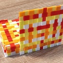
The 16 LEDs are divided into two groups, one of 10 LEDs and the other of 6 LEDs. It will explain the role of the two groups of LEDs and what the buttons use. I mounted the LEDs inside the transparent bands as you see in the graphic below.

The 10 LEDs in the lower group are meant to display the ten colors I chose to show the time. The color list can be changed from the SW1 button. The 6 leds above will show the time: the first two digits of the hour, the next two digits of the minutes and the last two will show the digits of the seconds. Another mode of display can be used, when both the top and bottom rows display the time with two vertical leds as shown in the figure below.

The display modes can be changed using the SW2 button. To download the program, available on github, please read my article about the Verbis clock as well as the articles mentioned above. I made the program so it can be tested on all three platforms, you must choose in the Arduino IDE the compilation for Wemos, ESP8285 or ESP8266, in addition at the source code a variable must be defined, "TransparentBand" for the Wemos and ESP8285 platforms and "Verbis" for the ESP8266 module from the Verbis clock platform.
Notes:
- there are two variants of mounting the LEDs in the transparent band. In the source code I showed both variants, comment out and in the lines alternatively in 'standardDisplay.h';

- if you have chosen a list of colors and the others do not interest you anymore SW2 can be used for example to choose between 24 hour and 12 hour format;
- you can mount LEDs in every holes of the transparent rings to try also other effects (the construction could be a beacon for example...).
Step 3: Components and Materials


Components, materials required:
- Transparent 3D printed bands, in 2 variants, large diameter and small diameter, I used transparent and white PLA, transparent PETG and translucent gray (I used the PETG prints, they are more flexible and look more beautiful);
- Double sided foam tape 3mm thick and tracing paper for the construction of LED light diffusers;
- Miniature Normally Open push-buttons;
- Wemos D1 Mini module;
- Micro USB cable;
- Power source with USB output 5V 2A;
- ESP8285 module (ESP-M3);
- 3.3v stabilizer module;
- 5.5x2.1mm DC connector female jack with cable;
- 5v 2A source with 2.5mm DC male jack;
- WS 2812 addressable LEDs (60leds/m) - 16 pcs;
- USB to serial converter;
- Wire, heat shrink tube, hot glue...
Step 4: Construction


I ordered the 3D prints from 2 companies specialized in 3D printing, they did not cost much and their quality is very good.
I cut from the LED strip a piece with ten and a piece with six LEDs. I glued the power and data wires at the beginning of the group with 10 LEDs and between the two parts.
I cut a piece of self-adhesive sponge (I didn't remove the yellow protective layer) and attached a strip of chalk paper on it. Then, with the help of an office paper puncher, I got some discs. I removed the piece of yellow round paper and glued the discs to the surface of the RGB LEDs.
Then followed the installation of the LED string in the transparent tape. Please note that the distance between the mounting holes in the tape is smaller than the distance between the LEDs so I had to model the tape so that the LEDs fit properly. I put a few hot glue points to secure the led strip.
Then I made the connections between the component parts according to the electronic scheme.
I loaded the program according to the variant. For the variant with the Verbis platform, please read the article for the construction and programming mode.
Simple, isn't it?
Step 5: How Is Working?
I thought I could best show the clock's operation if I made a video about it. You can watch this video below.
I hope you liked my article and in the future you might try to build this watch yourself. If you have any questions, queries, you can write to me if I will try to answer.
I wish you good health and I hope we will to get out of this complicated period for good.

Runner Up in the
Clocks Contest


